Introduction to Hardware Peripherals
Lately I have been doing programming for embedded systems such as the esp32 and esp8266, and additionally I did a course on embedded systems for my masters degree. This introduced me to the wonderful world of programming close to the hardware level, and inspired me to write this post about hardware peripherals.
What are Hardware Peripherals?
Hardware Peripherals are specialized pieces of silicon that are built into a processor. They are used to perform a diverse set of task. This includes controlling the processors clock speed, power management and communication with other devices. They are responsible for configuring the device operation and during operation are used to perform tasks in parallel with the main cores.
So what can these peripherals do?
Anyone who has ever looked into the data sheet of a microprocessor will know that these data sheets are long. The data sheet for the ARM cortex m7 CPU for example is about 2000 pages long. Which is to say that there are a lot of peripherals that can do a variety of things, for example:
- Analog Digital Converters (ADC) used for measuring analog signals
- Direct Memory Access Controllers (DMA) used for copying data from sensor to memory or the other way
- GPIO Interfaces used for pin management
- I2C and SPI Interfaces used for communicating with sensor devices
- PMC the power management controller
- Other Memory interfaces such as PCI or EBI
Using Peripherals
In order for us to use a peripheral, we have to complete a few steps:
-
Setup peripheral mode
-
Start peripheral task
-
Wait for peripheral to finish
All of this is done via memory mapped registers, which is to say that within the memory range of the processor there are dedicated areas of memory that do not map to a memory controller like an SDRAM, but are mapped to registers belonging to the peripherals. The peripherals use these registers as configuration values that change how the peripheral is working or if it is running, and some of the registers are not meant to be written to but instead are used to communicate the status of the peripheral back to the CPU.
All of this is described in the data sheet of the processor you are using. Every peripheral has a section describing what it can do, and what parameters can be changed via the memory mapped registers, as well as how the peripheral can be started, stopped and how to know when it is finished.
Since all of this is highly dependent on the platform you are using, it is hard to give you a clear cut way to use any peripheral. You will always have to refer back to the data sheet and look how to use the peripheral for your platform. But in order for you to get an idea on how to do this, let us look at an example.
Example
Every example is specific to the specific device we are using. For these examples we are going to look at the simple case of toggling a GPIO pin. The chip we are using is an embedded cortex m7 cpu, from atmel. It belongs to the atsame70 family of cpu’s. Datasheet
So all we want to do is let a led blink. To do this we will have to toggle the status of a pin, and all pins are managed by the GPIO peripheral. In the data sheet of this particular chip this peripheral is just called PIO. To be able to do this we first have to tell the PIO peripheral that it should take control of the pin and then tell it to configure the pin to be used as an output. After that we can change the pin state.
If you already looked into the data sheet you might have noticed so that there are multiple PIO peripherals and how the pins are mapped depends on the rest of the system. For the system that i am programming a led is connected to pin 19 on PIO C. So this is the pin I will be using in this example.
To achive an accurate timeout between turning the led on and off, we are going to use the real time timer peripheral on our device. It is in essence a configurable counter attached to a clock signal.
Let us do this in C
This example uses the C library provided by atmel which provides the correct memory addresses of the peripherals and exposes them to us as definitions and structures. By just using these we are automatically writing to the correct addresses.
	#include "atsame70.h"

	void timeout_ms(int ms) {
		// restart timer and set prescaler to count every 32 clock cycles
		// this corresponds to a 1ms clock cycle since the clock frequency is 32 kHz
		RTT->RTT_MR = RTT_MR_RTPRES(0x20) | RTT_MR_RTTRST;

		while ( (RTT->RTT_VR | RTT_VR_CRTV_Msk) < ms) {
			//wait for counter to have counted to desired timeout
		}
	}

	void blink_led() {
		//give control of the pin to the pio -> basically the running code
		ATSAME70_BASE_PIOC->PIO_PER = PIO_PC19;
		ATSAME70_BASE_PIOC->PIO_OER = PIO_PC19;

		while(true) {
			//turn led on
			ATSAME70_BASE_PIOC->PIO_SODR = PIO_PC19;

			timeout_ms(500);

			//turn led off
			ATSAME70_BASE_PIOC->PIO_CODR = PIO_PC19;

			timeout_ms(500);
		}
}
Timeouts
Since the device can vary it’s clock speed it is not desirable to implement a delay with just waiting a specified amount of clock cycles. Instead we are going to use the atsame70 Real Time Timer (RTT).
How to configure the RTT correctly can be read in the functional description in the data sheet. In short we have to configure the clock source since there are two at different speeds. Scale how many clock cycles trigger the counter and reset the peripheral for the new setting to take affect.
To do this we have to write to a memory mapped register:
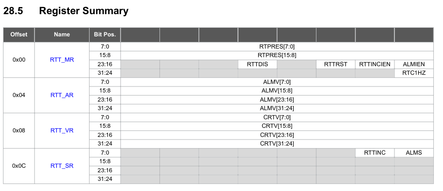
In the figure we can see all the registers that are connected to the RTT. All the values we need to configure are in the RTT_MR register. It is basically just a 32 bit value. But every bit has a meaning. The first 16 bits represent the 16 bit prescaler value, and there is also a bit to enable the peripheral and one to the reset it. Selecting the clock source is also done with one bit.
So what do we need to wait for a certain amount of ms:
-
Select the 32kHz clock src by setting the RTC1HZ bit in RTT_MR to 0
-
Setting the RTPRES 16 bit value to 32 in order for the counter to increase ever 32 clock cycles which corresponds to increase the counter value evey 1ms
-
Set the RTTDIS bit to 0 to not disable the rtt
-
Trigger the RTT reset by setting RTTRST bit to 1
All of these 4 steps can be done with one write to the RTT_MR register.
Afterwards the timer is running and we can read the value in RTT_VR to see how much time has passed.
Controlling the LED
The PIO peripheral that manages the pins of the device is a lot more complex than the RTT peripheral. Which means it has many more registers. Using these we can do fancy things like giving other peripherals such as the SPI peripheral control over the pins it needs to communicate.
But we are just interested in simply controlling a pin ourselfs. For this we need 4 different registers:
-
PIO_PER peripheral enable register
-
PIO_OER peripheral output enable register
-
PIO_SODR set output data register
-
PIO_CODR clear output data register
They all have the same structure so i am just going to show you one of them:
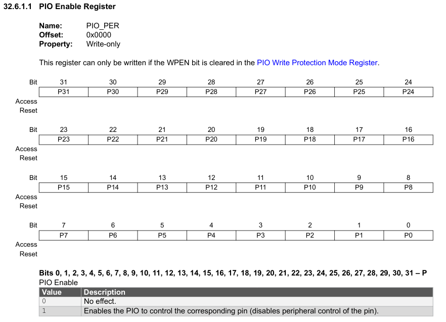
Basically for every pin controlled by the PIO there is a bit. So one PIO gives us control over 32 pins. To control a pin we have to do the following steps:
-
set PIO_PER pin bit to 1 to enable control of the PIO over the pin
-
set PIO_OER pin bit to 1 to set the pin into output mode
Now setting the PIO_SODR pin bit to 1 to pull the pin high and setting the PIO_CODR pin bit to 1 pulls the pin low again.
How does all of this look in Rust
For rust there is no official library from atmel, but there is a project called svd2rust that allows us to auto-generate a library that we can use to address the correct peripheral registers. All we need is the svd file of the processor we are using, this is an xml file describing all the peripherals and their register values.
	use atsame70q21::{Peripherals}

	fn timeout_ms(peripherals : & Peripherals, u32 ms) {
		let rtt = &peripherals.RTT;

		// restart timer and set prescaler to count every 32 clock cycles
		// this corresponds to a 1ms clock cycle since the clock frequency is 32 kHz
		rtt.rtt_mr.write( |w| {
			unsafe {w.rtpres().bits(0x20);}
			w.rttdis().clearbit();
			w.rttrst().set_bit()
		});
		while rtt.rtt_vr.read().crtv().bits() < ms {
			// wait for counter to have counted to desired timeout
		}
	}

	fn blink_led() {
		let peripherals = Peripherals::take().unwrap();

		let pioc = &peripherals.PIOC;

		//give control of the pin to the pio -> basically the running code
		pioc.pio_per.write( |w| w.p19().set_bit() );
		pioc.pio_oer.write( |w| w.p19().set_bit() );

		loop() {
			//turn led on
			pioc.pio_sodr.write( |w| w.p19().set_bit() );

			timeout_ms(&peripherals, 500);

			//turn led off
			pioc.pio_codr.write( |w| w.p19().set_bit() );

			timeout_ms(&peripherals, 500);
		}
	}
The logic of the rust code is exactly the same as the C example, and since all of the actual functionality we are using is provided by the hardware and not by the language specifics the code looks mostly the same.
I hope you liked this little excursion into bare metal programming, i am sure i will return with more blog post regarding similar topics while i keep experimenting more with rust on bare metal systems.